| Northern Utah
WebSDR KD7EFG Current Issues and Latest News |
|
Ongoing (long term) issues:
- The East-Pointing beam has been repaired and is working normally.
- See the 2-4 August, 2025 entry, below for details.
- Occasional power line noise issues.
- The power lines near-ish the WebSDR's remote receive site are likely 60+ years old and, as readers of this page, you'll know that their reliability is questionable with power poles falling down, insulators breaking and occasional very high noise levels - particularly when conductive "mud" rains down from dust blown off the flats around the Great Salt Lake.
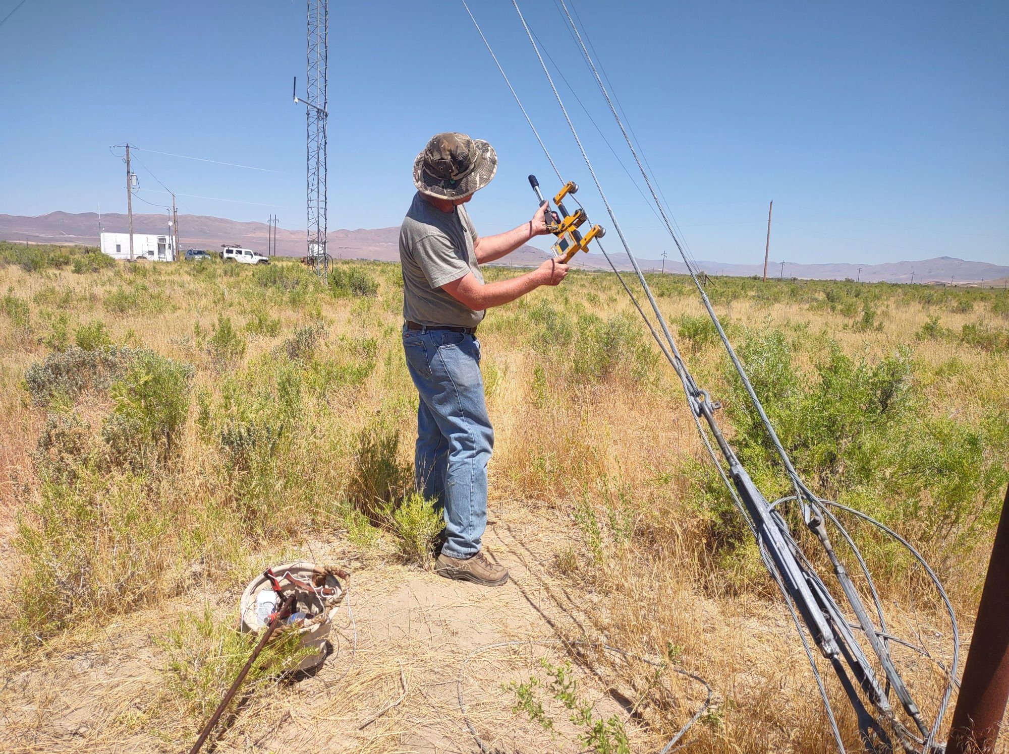
- It is a continual effort to monitor the noise floor -
occasionally "walk the line" and locate/identify specific noise sources
and pass this information to the power company: It's up to them
to (eventually) do something with this information - or not!
- As WebSDR #5's antenna is a northwest-pointing beam which is aimed at these power lines, emissions of noise from these lines will be noticed there, first.
- Investigation of new(er) WebSDR server software.
- We are looking into newer/other software for our public-facing WebSDR servers, but we haven't found anything that would suit our needs... yet. See the "New Servers" page (link) for more information.
