 |
Northern
Utah WebSDR
Receiving equipment
Narrowband "SoftRock" receivers |
SoftRock
receivers:
These receivers are the "High Performance" receivers used at the
Northern
Utah WebSDR and are based on the so-called "QSD" (Quadrature Sampling Detector)
mixers (sometimes known
as a "Tayloe" detector) 1
2
3 4
that use analog MUX switches to provide the "mixing" action.
This
mixer topology is well-used in commercial amateur gear - notably more
recent Elecraft gear - and it has the advantage of being both simple
and capable high-performance as well as being easy to interface with
conventional hardware - such as a standard audio-frequency sound card -
for final digitization. Essentially a direct-conversion
receiver,
the RF energy that is present +/- the center (local oscillator)
frequency is digitized up to the Nyquist limit (half the sample rate).
The receiver itself has two
conversion channels that are identical aside from the fact that the
local oscillators are 90 degrees out of phase with each other ("I" in-phase and "Q" -
quadrature) which, with a bit of math (addition and subtraction and
phase-shifting) allow the entire spectrum above and below
the center
frequency to be represented in software.
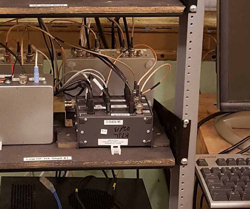
Figure 1:
Three SoftRock Ensemble II receivers in service.
Click on the image for a larger
version.
 |
There are two "SoftRock" receiver types in use on this WebSDR system:
- The "Softrock Ensemble II" sold by fivedash.com (link).
This receiver has a built-in local oscillator based on the
Silicon Labs Si570 (the
same chip used as the local oscillator in the Elecraft KX-3)
and can be tuned anywhere from about 1.5 MHz to 30 MHz via a USB
connection. This receiver can be purchased either as a kit (at around $65) or
as an assembled board (about
$89).
- The "Softrock II Lite" also sold by fivedash.com (link).
This is a simplified version of the Softrock Ensemble II in
that
it comes with an assortment of quartz crystals and extra capacitors so
that the builder can choose a 160, 80, 40, 30 or 20 meter frequency and
the front-end filtering is a bit simpler/less robust:
"Stronger",
band-specific filtering is done prior to the receiver in the RF signal
path so this isn't
important. It is
available only as a kit ($21).
Comment: Five-Dash
seems to be winding down its operations, so one or more of the above
kits may not be available now or in the future.
For our purposes, the two kits function identically in their role in
converting RF to audio as the mixer and audio amplification circuitry
of the two are pretty much the same. The "Softrock Ensemble
II"
kit has the obvious advantage of having a built in, tunable local
oscillator - but it is a much more expensive and complicated kit.
The Si570 synthesizer, while convenient to use, has the
disadvantage that it is not particularly stable with frequency -
indeed, the Elecraft KX3 uses a temperature sensor and a computer
lookup
table to maintain frequency stability, but the Ensemble II lacks this
so
its absolute frequency stability can be affected by changes in ambient
temperature. On lower bands like 160 meters this is not much
of
an issue, but on a higher band like 15, 12 or 10 meters this can amount
to several 10s of Hz change. Because we are using an
"outboard"
synthesizer for the "Softrock II Lite" kits, we were able to
substitute a TCXO (Temperature-Controlled
Crystal Oscillator) to obtain excellent frequency
stability - more on
this later.
Initially, we used three Softrock Ensemble II receivers for 160, 80
meter phone and 75 meter phone coverage, but a later upgrade included
the construction of a module with three Softrock II Lite receivers to
cover the entire 80/75 meter band, freeing those two units for coverage
of other bands as described below.
Both the "Ensemble" and the "Lite" receivers feed the RF directly into
the mixer (after
filtering, of course) which is then passed to low-noise
audio amplifiers - but this also means that these receivers are a bit
"deaf". For low bands like 160 and 75 meters - where both
noise and signal levels are quite high on a "full-sized" antenna like a
dipole this isn't too much of a problem, but on higher bands where the
intrinsic noise is lower - and the losses of the receivers' circuitry
is higher - it is increasingly important that some sort of RF
amplification be used: This, too, will be discussed later.
Receiver
modules using the Softrock II Lite receivers:
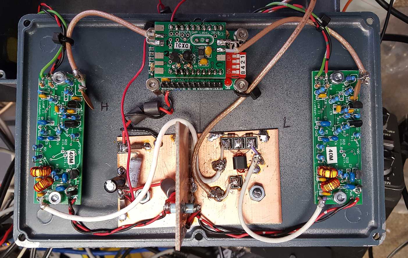
Figure 2:
Inside the dual 40 meter receiver module.
In the center is power supply filtering (on the left)
and a passive 2-way signal splitter (on the right)
with
the pair of Softrock II Lite receiver modules on each side.
In
the center
at the top is the ProgRock synthesizer, configured for two outputs.
The
receivers have been slightly modified to accept an external
frequency source in lieu of the original quartz crystals.
Remember that the local oscillator is four times
the actual receiver center frequency due to the on-board divide-by-four
counters to produce the needed quadrature signal.
Click on the image for a larger
version.
 |
As noted above, the "Softrock II Lite" kit uses quartz
crystals and the frequency selection is rather limited, so if we wish
to have flexibility in our frequency coverage we'll need to use
something else to provide our local oscillator. The device
chosen for this role is the inexpensive ($18) "Progrock" kit sold
by QRP Labs (link).
As the name implies, this functions as a sort of programmable
crystal (e.g. "rock")
and these devices, based on the Silicon Labs Si5351a (the same chip used to provide
the local oscillator of the Elecraft KX-2)
can easily
cover from about 8 kHz to well over 150 MHz - and may be coaxed even
lower/higher than that if one pushes it beyond its official specs!
What's more, these devices can output up to three
programmable frequencies at once (with
some limitations) which means that a single unit can
provide the local oscillators for up to three different receivers.
As delivered, these devices come with inexpensive quartz crystals that
are prone to drift with temperature, but for less than $3 they can be
retrofitted with a TCXO (Temperature
Controlled Crystal Oscillator) that "nails" down the
frequency with
part-per-million stability, giving them better frequency accuracy and
stability than many commercial HF rigs. The ProgRock kits are
typically programmed using DIP switches and a pushbutton for frequency
entry using binary-coded decimal (BCD)
but newer versions may be programmed via an asynchronous serial port.
For our purposes, only the DIP-switch programming is used as
there is no reason to be able to change the center frequency of a
receiver
remotely.
Figure 2
shows the dual 40
meter receiver module. On either side is a Softrock II Lite
module built for 40 meters with the ProgRock synthesizer at the top,
two outputs used to feed the receivers which have been slightly
modified (the addition
of a single capacitor, the removal of a different capacitor)
to accept an external input in lieu of the original quartz crystal.
The ProgRock itself has been modified to use a TCXO as its
frequency reference to provide a stability of approximately 1ppm over a
wide temperature range which translates to an on-frequency stability of
about +/- 7
Hz at 40 meters. It's worth noting that the local oscillator
frequencies
being
fed into the receiver modules operate at four times
the center frequency of the receiver because there
is
digital divide-by-four circuitry to provide the
quadrature local oscillator feeds for the QSD mixer.
In the lower-center, constructed "Manhattan" style - is a power supply
filter on the left and a 2-way passive RF signal splitter on
the
right, the latter sending equal amounts of received RF to each of the
two receivers. As noted above, additional RF amplification is
used to bring the signal levels up a bit and this will be discussed in
greater detail later.
Comment: Later
multi-receiver modules contain one amplifier per receiver board to
reduce possible spurious signals caused by local oscillator leakage
from the receiver module itself. Eventually, the 40 meter
receiver will be modified so that each receiver has its own RF
amplifier to improve isolation, for the reasons mentioned in the
discussion of the 20 meter receiver module, below.
Potential
issues with spurious signals:
As mentioned above, the ProgRock is capable of producing up to three
independent
frequency outputs at once, all from the same (tiny!) Si5351a
chip - but there is basis for some concern if one does this.
Using just a single
output, the signal is actually quite "clean", spectrally - far cleaner
in non-harmonic content than that typically obtained using a typical
DDS
synthesizer module - which is why
this same chip is the basis for many commercial and kit radios these
days. If more than one output is used, the spectral purity of
the
Si5351a chip suffers - but how much?
In the case of the dual receiver - where two outputs are used - if a
single, strong CW signal were injected into the receiver (say, -20dBm - a "50 over"
signal)
a number of low-level spurious responses could be seen in the
receiver's waterfall, the worst being on the order of 70dB (or more) down.
What this means is that if a "20 over" signal were present on
the
input (about -53dBm)
a signal
of S-1 or lower would result - but this would be at or below the noise
floor on nearly any HF frequency, anyway. Whether or not you
might think that this was poor performance it's worth pointing out that
many HF receivers do have
similar spurious signal performance numbers, these "deficiencies" going
unnoticed by the casual user - particularly on a busy band.
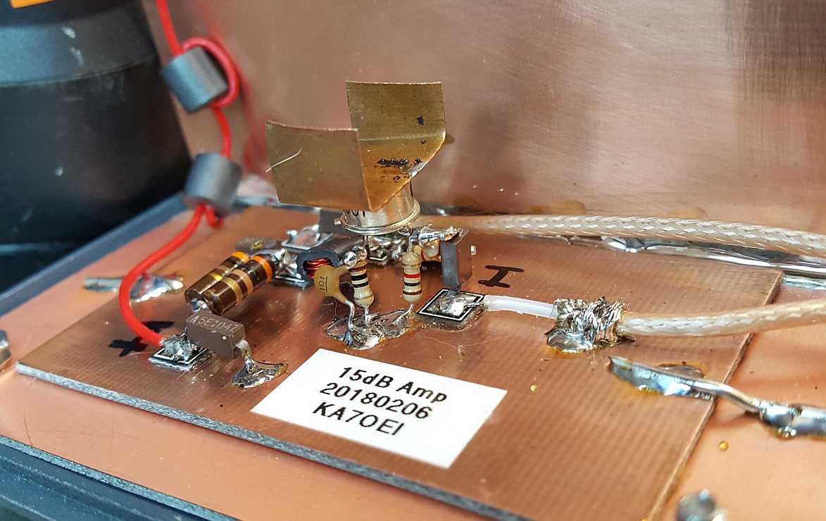
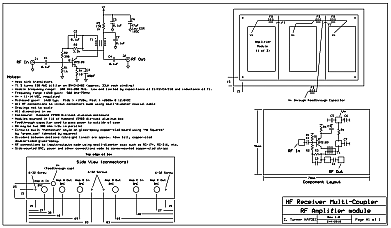
Figure 3:
Top: Close-up of the 2N5109 RF
amplifier - one of
three
contained within a single amplifier module. A later
modification of
these amplifiers included the addition of a 2dB resistive pad on the
output to assure unconditional stability
with reactive sources/loads.
Bottom:
Schematic diagram of the amplifier module
Click on an image for a larger
version.
 |
 |
RF
amplification using the 2N5109:
As noted previously, these "SoftRock" receivers - with no active
devices in the signal path prior to the mixer - tend to be a bit
"deaf". In theory, their audio outputs are pretty low-noise
with
microvolt-level RF signals appearing nicely at the output, but the
problem comes about when interfacing these same low-level audio signal
to sound cards. A typical good-quality sound card (such as those in the Asus Xonar
series) is able to "see" weak signals like this - but
there are
two other issues that tend to show up:
- Many sound cards tend to get a bit "noisier" as the audio
frequency increases. This is manifest by the low frequencies
being pretty quiet, but the noise floor at the higher frequencies
gradually increasing. Enough RF gain must be applied to
overcome this intrinsic noise at all covered frequencies.
- There is often noise around the "zero Hz" area.
Because
these SoftRock receivers are direct-conversion, RF frequencies near the
local oscillator get translated to low audio frequencies with there
being the so-called "Zero Hertz" hole for RF frequencies precisely on the
local-oscillator frequency caused by AC (capacitive)
coupling. Typically this hole is only a few 10s of Hz wide,
but
if an AM signal's carrier landed precisely in that hole, it would turn
into a carrier-suppressed double-sideband signal. Also near
"DC"
tends to be 1/F noise from the circuitry itself along with some
low-level AC mains-related hum - an inevitable result of the power
supply within the computer itself and slight circulating currents (e.g. ground loop)
between the receiver, connecting cables and in the sound card itself.
By boosting the RF signal a bit the two noise sources can be submerged
by RF noise coming in from the antenna - but there is
a delicate balance: Too much RF gain and the
high-signal
performance of the receiver will suffer, and too little gain, weak
signals are lost in the noise. "Barefoot" (e.g. without any amplification)
these SoftRock receivers will start to saturate/clip at about -12 to
-17dBm (a signal level
of about "60 over")
which means that one could "safely" add another 10-15dB gain without
much worry about a few very strong signals, or the cumulative
RF power of many signals on a band, causing overload. For
example, if the receiver were to start to overload at -25dBm (about "50 over")
it would take about 100 "20 over" signals on the band (not including overall noise)
to attain this much signal power: While not impossible, this
is unlikely to happen - even during contests.
To be "safe", one must keep in mind the following for any RF
amplification that is to used:
- The
RF amplification must be of high dynamic range and "clean".
Even with
a lot of signals on the input - particularly strong, shortwave
broadcast band signals that may be far removed from receiver's
passband, but still within the RF filter's passband, the amplifier
should not cause distortion.
- The RF amplification must be
pretty "quiet". The amplifier itself must have a reasonably
low "noise
figure" - that is, it shouldn't contribute much of its own noise to the
signals that pass through it.
- Where practical, RF amplifiers should be placed downstream
of band-specific RF filtering. This will prevent the
amplifier - and
receivers following it - from "seeing" more signal energy than
necessary, particularly from those signals that are distant in terms of
frequency from the receivers'
intended coverage.
A useful article on this topic (among
many) is one written by Gary, WB9JPS 5
where he discusses various requirements of signal amplifiers,
including gain and noise figure, in HF and VHF radio systems.
(An article
that comes to similar conclusions is one written by AB4OJ - see reference
8.) Gary's conclusion - which is
not
unique to this paper - indicates that conservative system
noise figure requirements of HF receive systems
are modest and along
the lines of:
- 1.8 MHz: 45dB NF
- 3.5 MHz: 37dB NF
- 14 MHz: 24dB NF
- 21 MHz: 20dB NF
- 28 MHz: 15dB NF
- 50 MHz: 9dB NF
- 144 MHz: 2dB NF
The
amplifiers discussed in the article by WB9JPS reminded me of a
November, 1984 article
in Ham Radio
magazine by Joe Reisert, W1JR 6
, where various topologies of amplifiers using the
venerable 2N5109 transistor are discussed- a device designed
specifically for
broadband, low noise, linear operation and is, more importantly, still
readily available! While both the W1JR and the WB9JPS
articles
describe amplifiers with better signal-handling performance and lower
noise than the common-emitter configuration that I used (see Figure 3 in the WB9JPS
article, which references a design by W7ZOI) the
performance of the amplifier is quite good and more than adequate for
the task at hand.
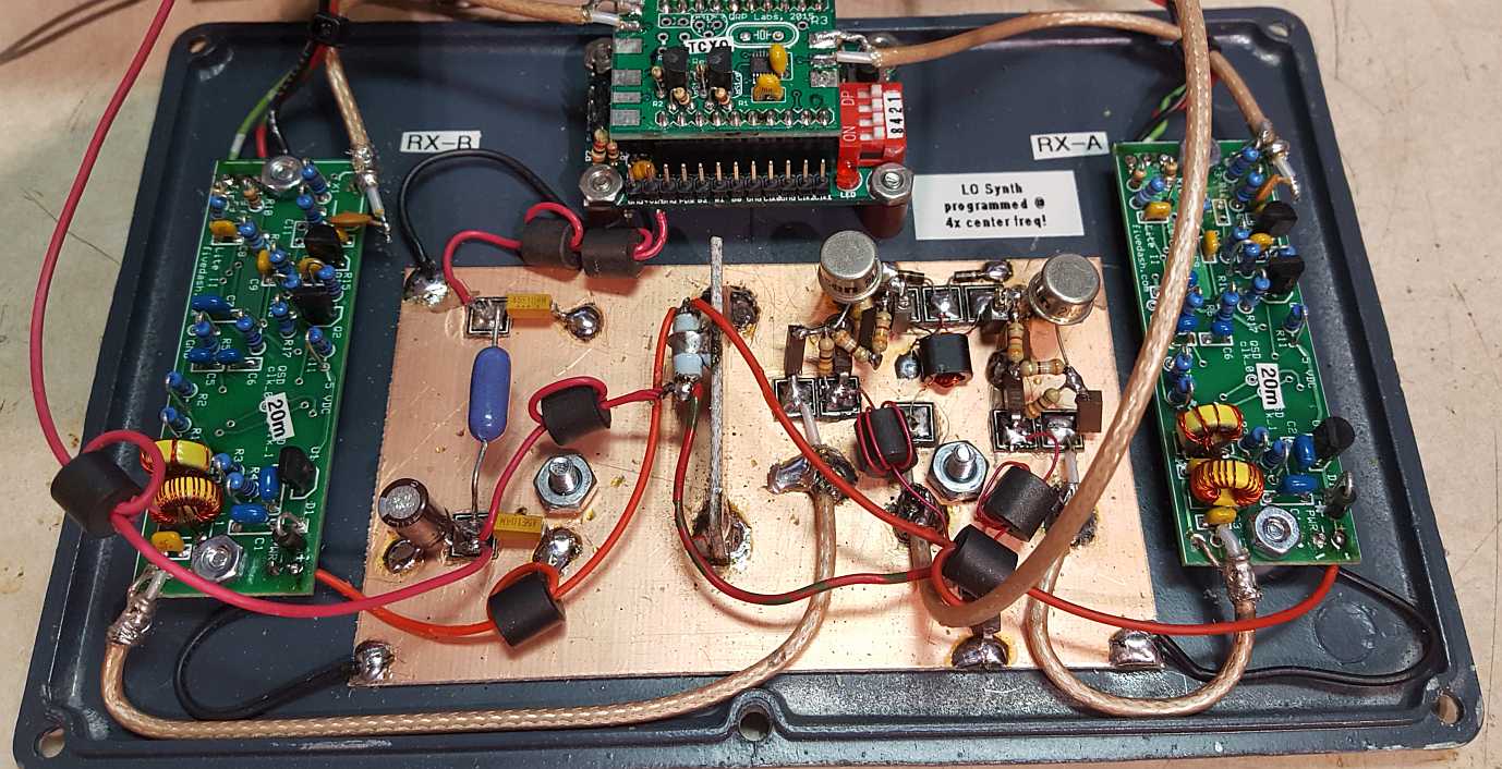
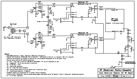
Figure 4:
Top:
The dual 20 meter receiver. This is very similar to
the 40
meter
receiver except that there is an RF amplifier for each receiver to
increase
isolation of the LO bleedthrough between the two.
Bottom:
The schematic diagram of the dual receiver module.
This
module could be used on any HF amateur band -
it is only the receivers and the programming of the LO that
dictate the frequency of operation. Remember: The LO
frequency is
four times
the actual receiver center frequency!
Click on the image for a larger
version.
 |
 |
A set of three of these amplifiers were constructed and housed in a
Hammond
1590D die-case enclosure using the circuit depicted in Figure 3 on this
page. Between each amplifier is a
"wall" of
double-sided, glass-epoxy circuit board material and each amplifier was
built on its own, private board using "Manhattan" ("dead bug")
techniques using "Me Squares" sold by QRPME (link)
that were (literally!)
glued down using high-quality cyanoacrylate
adhesive (e.g. "super"
glue.)
The usable frequency range of these amplifiers is on the order of 50kHz
through 200 MHz, but they are flat to better than 1dB over the range of
1.5-30 MHz. In testing these amplifiers they maintained very
linear
output (e.g. negligible
intermodulation distortion) at power levels over +20dBm (100 milliwatts).
Even though there are three amplifiers in the same enclosure,
the
isolation between them was around 100dB at 10 MHz degrading to around
80dB at 30 MHz.
The idea behind three amplifiers in one
enclosure was that they could be used as general purpose gain blocks:
If extra gain was needed somewhere, these would be available
to
provide it - and upon installation of the WebSDR, one section was used
with the 160
meter "Softrock Ensemble II" while another section was used for the
dual
40 meter receiver module depicted in Figure 2: This added
gain (13-15dB)
was
about right to allow the receiver to "see" the noise floor during
daylight hours, but not so much that receiver system performance was
compromised even when there were a lot of "big" signals during contests.
RF
amplification using the Mini-Circuits GALI74+:
More recently, amplifier "gain blocks" used at the WebSDR have been
constructed using the Mini-Circuits GALI74+ MMIC. This device
is
quite remarkable in its capability in that its gain is ruler-flat from
DC through at least VHF and usable up to at least 1 GHz. In
terms
of signal-handling capability, it compares very well with a
2N5109-based amplifier, having a typical 1dB compression level of about
+19dBm and a 3rd-order intercept point of around +38dBm. The
noise figure of this device is also lower than that of a simple
common-emitter 2N5109-based amplifier - typically a bit under 3dB
whereas the 2N5109 has an approximately 6 dB noise figure.
Another property is that the Gali74+ amplifier has a gain of
around 25dB at HF - about 10dB higher than that of a typical 2N5109
amplifier: While this extra gain is useful, it can also be a
liability if an appropriate signal-path analysis is not carried out.
Also important is that this device costs, in single quantities, about
as much as a 2N5109 transistor - and it needs fewer support components
to work.
At present, this circuit is being used in a few places where higher
gain and/or lower noise figure is desirable as discussed later.
Additional
receiver modules:
When the WebSDR system was first brought online the three Softrock
Ensemble II receivers were used to cover a portion of 160 meters and
most of the phone portions of the 80/75 meter band. At this
time
additional equipment was in the works that would be used to provide
coverage of all of
80/75 meters in three chunks and the entire 20 meter band in two -
all of these using SoftRock Lite II modules. As new modules
were
constructed using the Softrock Lite II receivers,
the Softrock Ensemble II, being capable of being tuned
anywhere,
became available for general use - such as providing coverage for "new"
bands or being used as a spare receiver in case of some sort of
equipment failure.
20 meter coverage:
By observation, it was known that amplification would be required for
the 20 meter SoftRock receivers so it was designed from the beginning
to include it - but there was a bit of a twist: One issue
related to any receiver using a QSD mixer is that it can have a
"significant" amount of local oscillator energy appearing on the
antenna port, and on the 20 meter modules this signal level was on
the order of -33dBm, or about "40 over" S-9. To the receiver
itself, this amount of signal is irrelevant as it cancels out and
doesn't appear as a strong "zero Hz" component, but on
the dual receiver modules the local oscillator for one receiver
appeared in the other and this "big signal" could have potentially
degraded performance - mostly in the form of a strong, off-frequency
signal that could mix in various ways with low-level local oscillator
spurious signals and the myriad of signals that might appear on a
"busy" band.
A degree of isolation (15-20dB) between the receivers was provided by
the passive 2-way splitter, but it was decided that each, individual
receiver would sport its own, private RF amplifier, adding another 20dB
or so of isolation, the end result being that one receiver would "see"
a signal of -60dBm (about
"10 over")
or less from the local oscillator of the other. Because these
amplifiers are relatively
simple -
and the parts cheap - the construction of the added circuitry was not
much of a burden.
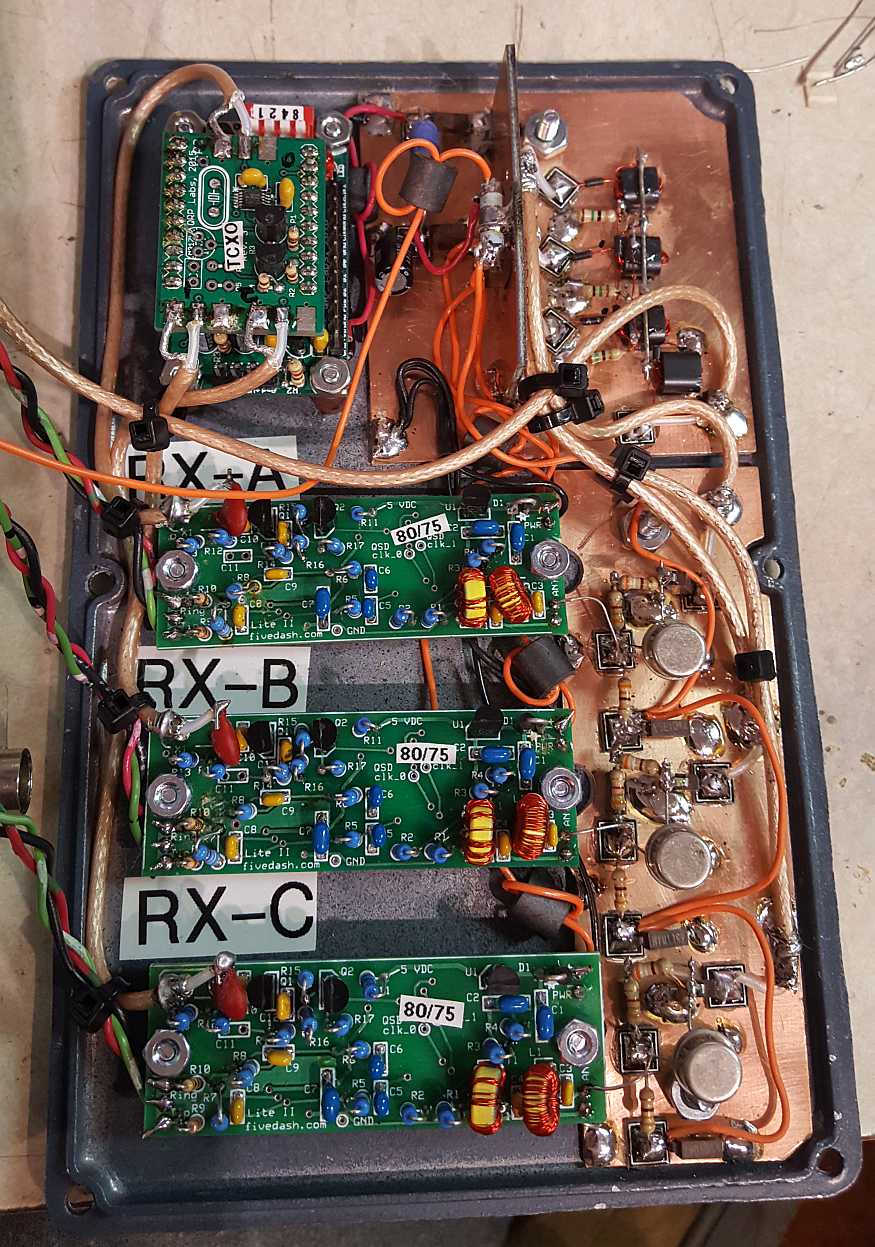
Figure 5:
Top: The "triple" 80/75 meter
receiver module.
Because there
are three receivers, the physical layout is different from the
dual receiver modules and like the 20 meter receiver, each
receiver has its own, private RF amplifier - both for gain
and LO isolation.
Bottom:
The schematic diagram of the triple
receiver module. Like the dual receiver, it's only the
receiver
itself and the programming of the synthesizer that determine
the HF band on which it operates. Remember: The LO
frequency is four times
the actual receiver center frequency.
Click on an image for a larger
version.
 |
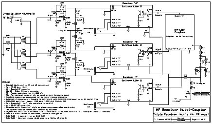 |
Figure 4 shows the completed receiver module. It is nearly
identical
to the dual 40 meter receiver module in that it uses a single ProgRock
synthesizer to to provide the local oscillator signals for both
receivers. If you look closely, you can see that there are
two
transistor amplifiers on the right-hand side of the copper-clad board
in the bottom-center, following the 2-way splitter and each one feeding
a receiver.
In testing on the workbench, the "MDS" (Minimum Discernible Signal)
of each 20 meter receiver was better than -127dBm (e.g. 0.1 microvolts in a 50 ohm
system)
indicating that they were as sensitive as they needed to be:
In other
words, this receiver was more than capable of hearing its fair share of
ionospheric noise when connected to an HF antenna and as such, more
sensitivity would not improve the ability to "hear" weak signals!
80 and 75
meter coverage:
It is somewhat inconvenient that most amateur bands are sized in
multiples of 100
kHz but audio sound cards have sample rates of 96 or 192
kHz. In the case of the U.S. 40 meter band we would need two
192 kHz
sound cards to fully-cover the 300 kHz-wide band. A somewhat
similar situation exists on the U.S. 80/75 meter band, which covers
from 3.5 to 4.0
MHz where we would need three
receivers to cover the entire band. It is convenient that the
ProgRock can
output three simultaneous outputs, so another receiver assembly was
constructed using three
Softrock Lite II modules.
The picture in Figure 5
shows
the layout. In the upper-left corner is the ProgRock
synthesizer
and like its counterparts, it, too is equipped with a 1ppm TCXO.
Below it are the three, identical Softrock Lite II modules
and to
the right of those, one for each receiver, are three RF amplifiers.
In the upper-right corner is a three-way splitter that
divides
the signals to the receivers equally and provides a bit of additional
LO isolation between the receivers and on the other side of the divider
is the same type of power supply filtering found in the other receiver
modules.
Figure 5
also shows the diagram of
the triple receiver module, the circuitry being representative of that
in the other two modules. If you look carefully you will
notice
that the RF amplifiers in the receiver modules are slightly different
than that depicted in the WB9JPS article - and is, in fact, a direct
"quote" of one of the amplifiers discussed in the November 1984 W1JR
article. The main difference is that these amplifiers lack
the
output balun/transformer which somewhat reduces the large-signal
performance, but because these amplifiers are placed "downstream"
bandpass filtering that is specific to an amateur band, they
will
not be "seeing" much of the HF spectrum and will be dealing with fewer
signals, overall.
References:
- Youngblood,
Gerald (July 2002), "A
Software Defined Radio for the Masses, Part 1" (PDF), QEX,
American Radio Relay
League: 1–9
- Youngblood,
Gerald
(Sep–Oct 2002), "A
Software Defined Radio for the Masses, Part 2" (PDF), QEX,
American Radio Relay
League: 10–18
- Youngblood,
Gerald
(Nov–Dec 2002), "A
Software Defined Radio for the Masses, Part 3" (PDF), QEX,
American Radio Relay
League: 1–10
- Youngblood,
Gerald
(Mar–Apr 2003), "A
Software Defined Radio for the Masses, Part 4" (PDF), QEX,
American Radio Relay
League: 20–31
- Johnson, Gary, "Measurements
on a Multiband R2Pro Low-Noise Amplifier System, Part 2" (PDF) (From the Web Archive)
- Reisert,
Joe, (November, 1984), "High Dynamic Range Receivers, Ham Radio.
A .PDF of the November, 1984 Ham Radio Magazine may be found HERE: The article begins on printed page 96, or page 100 of the .PDF.
- Turner,
Clint, (March, 2018), "Managing
HF signal dynamics on an RTL-SDR receiver"
- Farson, Adam, "Antenna and
Receiver Noise Figure"
Pages about other receive gear at
the Northern Utah WebSDR:
- RTL-SDR Dongle-based receivers
- Described here are the "not high performance" receivers using the
ubiquitous RTL-SDR dongles. These receivers cover up to 2
MHz of
bandwidth, but their limited A/D bit depth (only 8 bits)
means that they can suffer from too much and/or too little signal input
- often depending on band conditions. Included on this page
is
information about how to make the most of these as well as helping to
manage when multiple RTL-SDR dongles are used on a Linux-based system.
- RF Downconverter for RTL-SDR
receivers
- While there are RTL-SDR dongles that contain built-in upconverters to
allow reception across the entire HF spectrum, this may not be the best
way to do it. When receiving frequencies at or above the
Nyquist
frequencie(s) on HF, one can downconvert to lower frequencies and get
good results, all described on this page.
- An AGC block for RTL-SDR receivers-
Because RTL-SDR dongles have only 8 bits of A/D, their dynamic range is
limited. While one can adjust the gain to fit their useful
signal
range "window", HF band conditions change constantly, making it
impossible to keep one of these receiver's limited dynamics optimized.
Preceding an RTL-SDR dongle with proper filtering and an AGC
circuit can make the best of these devices.
- RF Distribution and filter system
- Absolutely essential to any receive system is the means by which RF
is distributed - and filtered, the means by which this is done at the
Northern Utah WebSDR being described on this page.
Go to the
main "RX Equipment page.
Additional
information:
- For general information about this WebSDR system -
including contact info - go to the about
page (link).
- For the latest news about this system and current issues,
visit the latest news
page (link).
- For more information about this server you may contact
Clint, KA7OEI using his callsign at ka7oei dot com.
- For more information about the WebSDR project in general -
including information about other WebSDR servers worldwide and
additional technical information - go to http://www.websdr.org
Back to the Northern Utah WebSDR
landing page


