It is common to use a WebSDR as an "auxiliary" receiver (or main receiver if your local noise is really bad!)
and this means that when you transmit, your signal may be received by
the WebSDR and get back into your transmit audio - usually via
acoustical coupling - and cause an "echo" that both you and others listening may hear via your microphone.
Other than wearing headphones - which doesn't spare you from your own,
delayed audio in your ears that can be very distracting - there are
several ways to avoid this:
Use the "Mute"
button near the volume control on the WebSDR. If you click this,
it actually stops the audio at the WebSDR, reducing its processor load
and network bandwidth..
Many "multimedia" keyboards have a button on them - usually
along the top row - that, when pressed, will toggle the computer audio on
and off. These buttons/keys often have a symbol that looks like a speaker with a diagonal line through it.
Some newer browsers (recent versions Firefox)
have, in their tab along the top of the screen, a very small speaker
icon when they are at a site that has embedded audio. You can
click on that speaker icon on the tab to mute the audio, at which point
the icon will switch to a speaker with a diagonal line through it - but remember that you muted it that way when you want to hear the audio again!
Muting using this tab may be more convenient since the speaker
icon can be visible even if you have hidden the window with the WebSDR.
On your computer/operating system it may be possible set up a shortcut or "hot" key to mute/un-mute the audio.
Turn down/off your computer speaker.
Figure 1: A diagram of two circuits that can mute your computer's when you transmit to avoid the "echo".
Both versions include an "extra" contact that may be used to key an external amplifier, but this portion may
be omitted if you don't plan to use one. An error was corrected from the original diagram - see text.
In the vast majority of cases, the left-hand circuit will suffice: The only difference between it and the right-
hand circuit is that the latter opens the ground path between the computer and the speaker which may
be useful of you hear some of your transmit audio getting into the speaker via RF pick-up. Click on the image for a larger
version.
All of these require manual intervention and become cumbersome if you
are engaged in quick and/or frequent band-and-forth, but there's
another way: Audio muting keyed by your transceiver.
The (simple!) circuit(s):
Th circuits depicted in Figure 1 are very simple: The audio from your computer to your speakers is routed through a set of normally closed
relay contacts. When the relay is energized by the radio going
into transmit, the contacts are opened, muting the audio from the
computer.
The circuits depicted in Figure 1are
"old school" using relays: Relays were chosen because they
are cheap, simple to use and offer good isolation at DC, audio and even
RF. Both versions show the keying of an external amplifier, but
if you don't need to do that you can just leave that part out, needing
just one DPDT (double-pole, double-throw) relay.
The components involved aren't at all critical: It's recommended the small-ish relays with low-voltage coils (24 volts or DC or less) be used. D1 is important as it suppresses the (high!) voltage from the relay coil(s) when they are de-energized and the magnetic field collapses: Do not omit it!
Using with an amplifier:
The advantage of using relays is that it will work with practically
any amplifier, regardless of its keying voltage. The only point
of concern might be if you get a slight "pop" in the audio when you
un-key the amplifier: If your amplifier has a relay, it may be
that its coil's electromagnetic field is collapsing and generating a
high voltage/arcing across RY2's contacts and the a bit of this can
couple into the computer audio: The optional "snubber" network mentioned on the diagram
should minimize this.
Note: There had originally been an error in the diagram on the right-hand side - the "Slightly Fancier" version - (corrected February, 2025) in which the amplifier keying had been connected to the "N.C." (Normally Closed) relay contact, resulting in the amplifier always being keyed. This should have been connected to the "N.O." (Normally Open) contact and has since been corrected.
Comments on radios' keying circuits:
While most "base station" radios have relays in them to key an external amplifier, some "portable" (usually QRP)
radios use transistors instead, so it would be a good idea to check the
voltage and current ratings on that output. If its keying circuit
can handle 15 volts or more and more than the current drawn by the relay(s) in the circuit, you are all set.
Note that transistor-based keying circuits are usually polarity-sensitive and ground-referenced (e.g. a positive signal on the external keying output gets "grounded" when you key the radio) so you would want to make sure that the keying line is connected appropriately (e.g. one side of the relays is tied to V+ and they are activated by "grounding" the other side of the coil.)
Another method of muting: Cutting power to the speaker.
While it is preferred that one simply mutes the audio to
the speakers, there are some powered computer speakers that can be
susceptible to RF - that is, you hear distorted voice through the
speakers when you transmit. In many cases building the circuit on the right hand side of Figure 1
will take care of this as it completely disconnects the ground lead
from the powered speakers, eliminating a possible RF current
loop. To
find if this will work for you, try transmitting with the audio lead
from the computer disconnected: If it's quiet, when you transmit, this will probably work.
Some computer speakers are so sensitive to RF that this may not be enough and another method may be required: Turning off the speakers' power when you transmit.
This
would be done the same way as one interrupts the audio: Wire a
normally-closed contact from the relay in series with the DC power to
your speakers. This is easily done if your powered speakers use an
external DC "power cube" - but if your speakers are high-powered or
have a built-in mains (AC)operated
power supply, this may not be either practical or safe. In other
words, this may not be applicable to all external "powered" speakers.
The
down-side of cutting power to the speaker is that the audio may persist
for a short time after the radio is keyed as its power supply
capacitors discharge. In addition to this, there may be a "click" or
"thump" in the speaker as its power is removed and/or re-applied: Whether
this is objectionable depends on how badly your speakers might do this
and whether or not it bothers you.
Powering the relay circuit:
The relay requires an external source of power - 11-15 volts being
fine for a typical "12 volt" relay. Out of convenience, the
prototype was powered from a "wall wart" (power cube)
that I had kicking around: It's official rating is "9 volts DC"
(unregulated) but because it consists only of a transformer, full-wave
diode bridge and a capacitor, its voltage is around 12-15 volts under
no/light load - perfect for this application. Because the relay
only consumes a few 10s of
milliamps when keyed, the current rating of this wall transformer could
be as low as 100 milliamps: It does to have a capacitor-filtered output (but no need for regulation) or else the relay will chatter. It is recommended that you NOT
use a switching-type power supply for this as that will likely produce
a bit of RF noise: If you have a candidate power cube and it
feels as though its box is empty (it has no "heft" to it) then it's likely a switching type.
If one side of the radio's PTT relay is (or can be) grounded (which is usually the case)
it is possible to power this circuit from the same "12 volt" power
supply as that which is running the radio. If you do this, be
sure to include a fuse (no more than 1 amp) in the power lead, near its connection to the rig's power supply to protect against accidental short-circuits.
Batteries may be used, too!
If you use 5 volt relays, it is also practical to power this circuit
using four AA or AAA cells in series. This has the advantage of
providing a completely-isolated power supply and being able to avoid
the inconvenience of yet another cable connecting to the circuit.
5 volt relays should easily be able to tolerate an extra volt or
so from the "6 volts" of four alkaline cells in series (which happens only when they are fairly new) so there is no
need to include a resistor.
A set of four AA alkaline cells should be capable of providing at least
50 hours of continuous key-down which means that if you are using these
for SSB and you are often on the air, a set of batteries will last a
year or so: If "C" or "D" cells were used, the longevity would be
about that of their shelf life! If
you run modes that require the transmitter to be keyed for long periods
of time - like CW or some digital modes - you may not want to use
battery power.
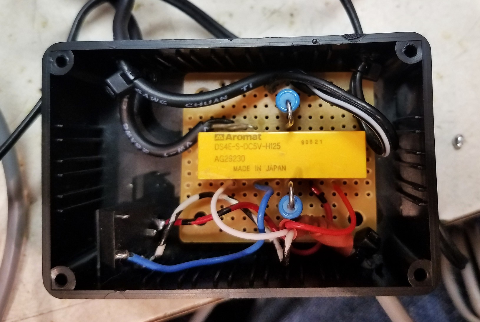
Figure 2: Inside the audio muting box. In the bottom-right corner is a "stereo" 3.5mm audio jack into which the external (powered) speaker plugs. For convenience, all components were mounted and connected to a small piece of phenolic "prototype" board. Click on the image for a larger version.
"But I don't have any 12 volt relays handy!"
If you have different-voltage relays on hand, you can use those - just
make sure that your power supply voltage is appropriate for them.
If all you have is 5 volt relays and your only convenient
voltage source is 13.5 volts from your radio, you can use series
dropping resistors, calculated as follows.
Measure the resistance of your 5 volt relay's coil. Let's
assume for this example that your relay's coil measures 185 ohms.
Calculate the current that the relay would draw at 5 volts.
Using Ohm's law, we divide the voltage by the resistance - so
5/185 = 0.027 amps (27 milliamps).
Calculate the amount of voltage drop that you need by subtracting
the rated relay coil voltage from our power supply voltage . If
we have 13.5 volts available, we need to drop (13.5 - 5 = ) 8.5
volts.
Calculate how many ohms it would take to pass the current
calculated in step #2 at the voltage calculated in step #3. In
this case, we divide the voltage by the resistance, so ( 8.5 / 0.027 =
) 314 ohms.
The two most common resistor values close to our example 314 ohms
are 330 ohms and 270 ohms - but because we can get away with +/- 20%,
either value will be fine.
Now calculated the power dissipation in that resistor. For
this we multiply the current by the voltage drop, so we do (8.5 * 0.027
= ) 0.229 watts. This is pretty near the maximum rating of a 1/4
watt resistor, so we would use a 1/2 watt resistor if we have one
on-hand, but because it's being used only intermittently (e.g. while
you are talking) a 1/4 watt resistor will probably be fine.
Some relays (reed types, those with built-in diodes)
can be polarity sensitive. If the relay doesn't close when you
apply voltage, try reversing the applied voltage's polarity.
To minimize the possibility of the relay's coil causing a "click" in the
speaker audio when you unkey, it would be a good idea to put the
reverse diode (D1 in the drawings) across the connection to the relay
coil to suppress the transient voltage that would otherwise
result.
If you are building the 2 relay version,
unless both of your relays are identical, you'll want to do the
calculation for each relay. If both of your relays are identical,
and they are both 5 volts you can wire them in series for
10 volts total, and then do the calculations for that, taking into
account the fact that the coil resistance will also be doubled.
An as-built example:
Here's an example of the "bare minimum" audio muting box depicted on the left side of Figure 1(above). Not only does it disconnect the audio going to the computer speaker, a third contact is used to key an amplifier.
The constructed unit can be seen in Figures 2 and 3. A few notes on the construction:
A small, plastic project box was used to house the unit with the
simple circuit constructed on a piece of perforated prototyping board.
On the box is mounted a 3.5mm "stereo" ("TRS") audio jack: The audio cable going to the speakers plugs into this connection.
A 5 volt relay was used, but a 13 volt unregulated "wall wart"
powers this device. This wall wart is an older transformer type
and not
a switcher so it cannot cause radio frequency interference. This
power source is completely isolated from anything else so there is no
risk of a ground loop.
A pair of 100 ohm resistors (the blue devices) were wired in series on either side of the relay's 120 ohm coil (because it was convenient to to so)
to drop the 13 volts down to approximately 5 volts. The resistor value calculated
using the steps above was 180 ohms, but 200 ohms is "close enough"!
The relay used is a 4 pole, double-throw (4PDT) relay that I happened
to have on-hand. If I didn't happen to have a 4-pole relay I
would have used a pair of DPDT relays: If they had been 12 volt
relays, their coils would have been wired in parallel, but if they were
5 volt relays I'd have wired them in series and used a dropping
resistor. This
relay is an Aromat DS4E-S-DC5V-H125 or an Omron G6A-434P-ST20-US-DC5 in case you are wondering:
There are 12 volt versions of these relays. This relay
happens to be polarity-sensitive.
Not visible in any of the pictures is a diode on the bottom of the board, across the
relay coil, used to suppress the transients that result when a relay
coil is de-energized.
A female phono ("RCA") jack is on the keying line to the amplifier, so a short cable with a male phono connector (seen in Figure 3) connects to it.
A female phono jack has the wires that are connected to "key"
this relay: This plugs into a male phono jack from the amplifier
keying relay on the transceiver.
There is a medium-length (about 2 feet/50cm)
shielded stereo audio cable with a male 3.5mm connector on it that is
plugged into the computer's audio output. Just visible in Figure
3 (this is the gray cable to the right)
this cable also has a several turns of it passed through a ferrite tube
to minimize the possibility of RF to/from the computer.
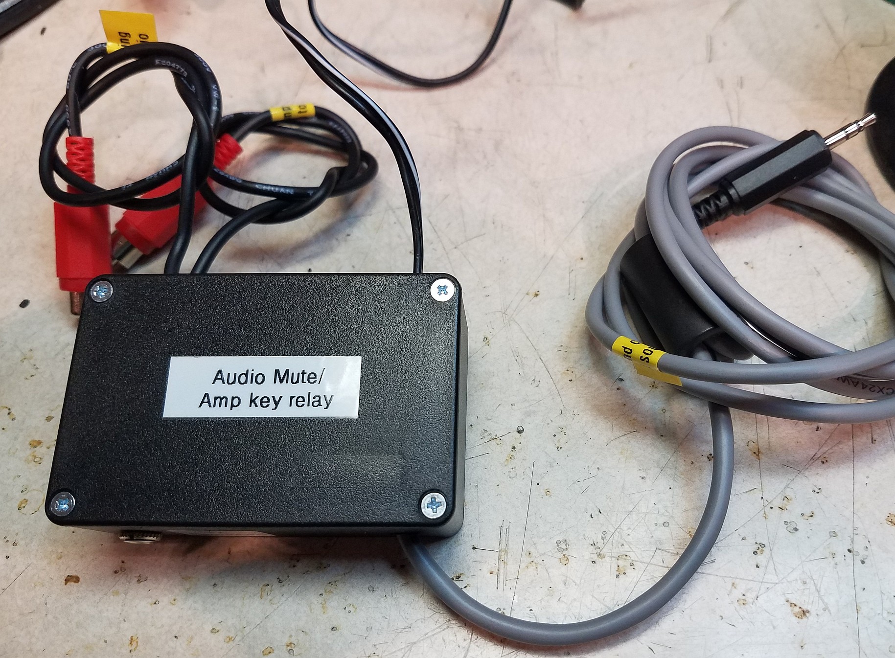
Figure 3: The outside of the muting box. In the upper-left are the
two cables with phono plugs: One goes to the transceiver's keying
line and the other connects to the amplifier. On the right (the gray cable)
is the audio from the computer and on this cable can be seen a ferrite
tube that is used to minimize the possibility of RF being
conducted on this line. In the upper-right corner of the box
is a black and white cable that goes to the filtered/unregulated
transformer-type "wall wart" used to power the relay when keyed. Click on the image for a larger version
Conclusion:
When tested, the circuit described works perfectly.
One
thing to remember is that any web-based receiver will have a slight delay as compared to a local, "real time" receiver
meaning that when you un-key, you'll probably hear the last syllable or
word that you transmitted coming back to you. While this may be
slightly distracting, echoes like this can never be heard over the air because this
circuit guarantees that your speaker(s) will be muted any time that you
key your radio.
Additional
information:
For general information about this WebSDR system - including contact info - go to the
about
page.
For the latest news about this system and current issues, visit the latest news page.
For technical information about this system, go to the technical info page .
For more information about the WebSDR project in general -
including information about other WebSDR servers worldwide and
additional technical information - go to http://www.websdr.org